Nitrogen can be produced onboard by Nitrogen generation system by following three ways :-
- The pressure swing absorption method .
- The membrane method
- The main vaporizer to vaporize liquid nitrogen supplied from the shore.
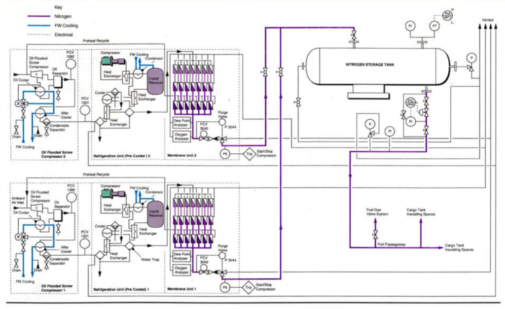
On LNG carriers, nitrogen is normally produced using the membrane method. The nitrogen production system normally consists of two equally sized nitrogen generator units. Normally, the generators are located above the main deck level in the engine casing. The mode of operation is dependent on the requirement and consumption of nitrogen.
This system generates nitrogen using the membrane method.
The nitrogen produced is used for the following purposes:
- Feeding of cargo tank insulation spaces.
- Purging of fuel gas supply lines and boiler furnaces.
- Purging of manifolds.
- Seal gas for cargo compressors.
- Fighting vent fires
- Fitting emergency cargo pump
Table of Contents
ToggleWhat Nitrogen Generation System consists of ?
For a typical membrane-type nitrogen generators onboard an LNG tanker of 130,000~145,000 m3 capacity.
The membrane-type nitrogen generators comprise of:-
- An air compressor unit with an oil separator.
- A freshwater cooler.
- A refrigeration (pre-cooler) unit.
- A system of several filters.
- Seven sets of membrane modules.
How Nitrogen Generation System work ?
The system uses hollow fiber membranes to separate air into nitrogen and oxygen. The principle of separation is based on the selective permeation of nitrogen and oxygen as each gas has its own
characteristic permeation rate.
Nitrogen permeates slowly whereas oxygen, carbon dioxide and water vapor permeate fast through the membrane due to the difference in molecular size of each constituent. This allows the separation of nitrogen from oxygen.
The membrane modules consist of a bundle of numerous hollow fibres. When clean, oil-free and dry compressed air is fed into the membrane modules pure nitrogen is obtained at the exit. The unwanted oxygen-enriched air is vented to the atmosphere or recirculated to the compressor
inlet.
System Components of Nitrogen Generation System ?
Air Compressor
Outside air is compressed by an air compressor to a nominal working pressure of 13 bar gauge. The bulk of the lube oil carried over with the compressed air is removed in the lube oil separator before it is cooled and returned to the compressor oil sump.
Fresh Water Cooler
The oil-free air is itself cooled by fresh water from the Deck Cooling Fresh Water System.
It then flows through a water separator for separation of moisture content before being filtered.
Refrigeration (Pre -Cooler ) Units
The compressed air is led through a series of the refrigerant cooler and air/ heat exchanger in the pre-cooler unit where impurities are removed and water is further separated down to a dewpoint of approximately 5O degree C.
System of Several Filters
The remaining oil vapours and aerosol are removed by an oil filter (0.0 03 mg /m 3 ). Finally, before entering the membrane the feed air is filtered by a carbon filter (0.1 microns) and a dust filter (0.01 microns).
A control valve prevents pressure build-up upstream of the membrane system. A mother control valve is pre-adjusted in such a way that the pressure upstream is maintained below the compressor switch point.
Seven Set of Membrane Modules
- The flow of compressed air is led into the membrane system. The separation of nitrogen, oxygen and water vapour takes place in the membrane modules.
Nitrogen exits at the bottom of the set of modules at about the same pressure as the entering air and the gases (oxygen, water vapour and carbon dioxide) are purged to the atmosphere. - The capacity of each module is pre-adjusted by needle valves. The adjustment is made to give a set flow for an output with the same oxygen content from each module irrespective of the characteristics of the individual modules which can be slightly different.
- The purged flow from the first two modules of each set is very rich in oxygen, water vapour and carbon dioxide and is, therefore, discharged to a safe area. The purged flow from the third module with much less composition of the unwanted gases is recycled to the compressor inlet thus optimizing the separation process.
- The nitrogen flow from the membrane outlet in order of sequence is via a control valve, a non-return valve and a pneumatic operated 3 – way ball valve. The control valve acts to keep the flow out of the membrane at a pre-adjusted oxygen level.
- At start-up, the pressure in the membrane system is slowly built-up. During this time the 3 -way ball valve is in the blowing off position. Three minutes after start-up, if the oxygen content is below the alarm setting of the oxygen analyzer (normally at 3% volume) and the dew point below – 55 degree C, the nitrogen product is directed to the system outlet and into the storage tank.
A small quantity of the nitrogen product (2.5 m3/hr) at 0.2 to 0.3 bars is recirculated into the feed air inlet to the membrane banks. A control valve is used to regulate the flow of the purged nitrogen through a pipeline of 8.0 mm diameter with a 2.0 mm or if ic e plate, and a non-return
valve prevents feed air from bypassing the membrane banks.
With this arrangement, the membranes are continuously purged with nitrogen whilst the compressors are shut down and the generator unit can almost immediately go on production mode when required.
How to store Nitrogen ?
The nitrogen produced is stored in a 12m3 pressure tank with a maximum service pressure of 8 bars. The stand-by Nitrogen unit starting pressure can also be adjusted as necessary. If the pressure is further reduced the second unit will also start. The pressure downstream of the storage tank is adjusted at 2.5 bars.