
Leading maritime community ! [email protected]
The Gear Pump is a rotary pump, a positive displacement type, used for pumping liquids.
Table of Contents
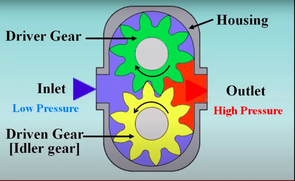
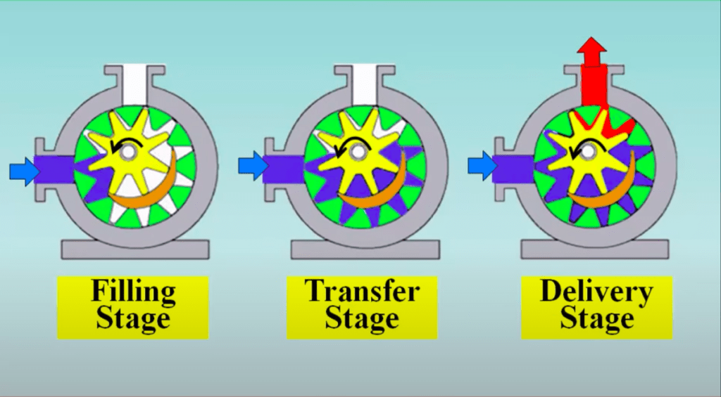
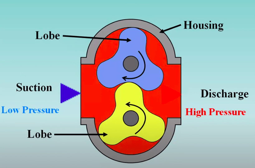
ToggleFluid comes to the inlet side and when the fluid moves forward due to the vacuum created behind the teeth of two gears, it starts getting trapped inside the teeth of the gear.
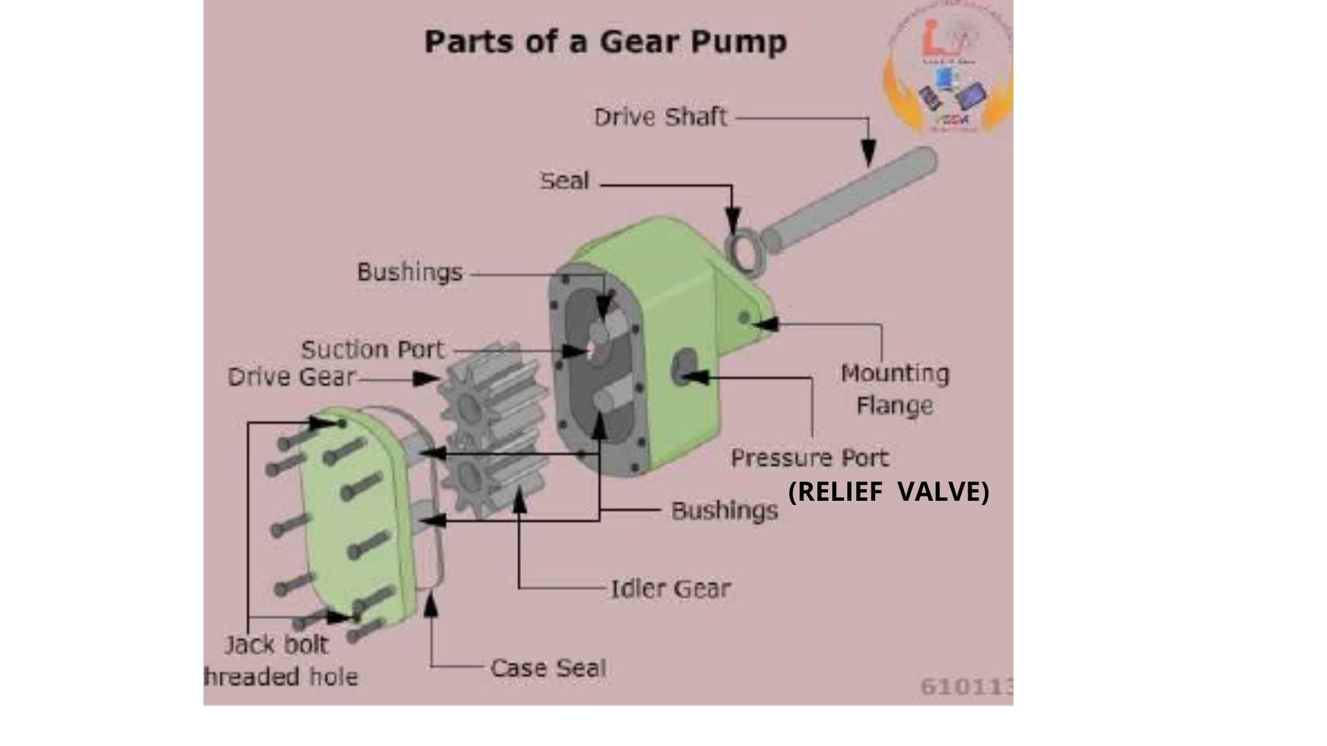
This trapped liquid passes through the region of fine clearance between the casing and teeth. Since there is no space to go anywhere, trapped liquid gets compressed and when the outlet side comes, this pressurized fluid rush towards the outlet of the pump. The relief valve monitors the pressure of this coming fluid and performs accordingly.
Note:- The mechanical clearances are small in the order of 10-micron metres. The tight clearances, along with the speed of rotation, effectively prevent the fluid from leaking backwards.
Backlash is the small gap provided between the two gears. It is important because due to heat, little expansion of teeth will be there.
If we don’t have backlash so when the pump rotates in opposite direction by mistake, so the sudden load comes on to the motor and it will trip on overload
There are mainly four types of the Gear pump. They are as follows –
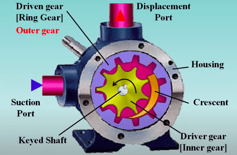
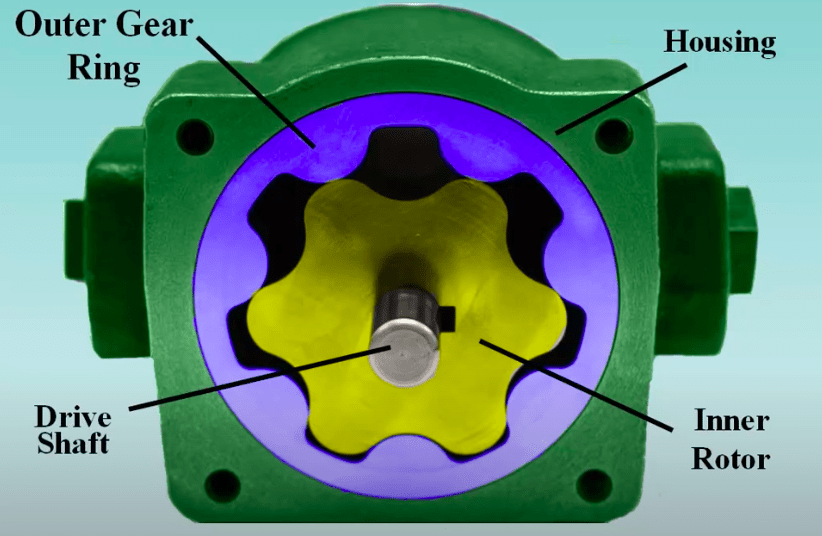
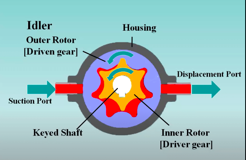
A Gerotor is a positive displacement pump. The name Gerotor is derived from the generator. A Gerotor unit consists of an inner and outer rotor. Gerotor pumps are internal gear pumps without the crescent. The pump consists of a pair of gears which are always in sliding contact, the internal gear has one more tooth than the gerotor gear.